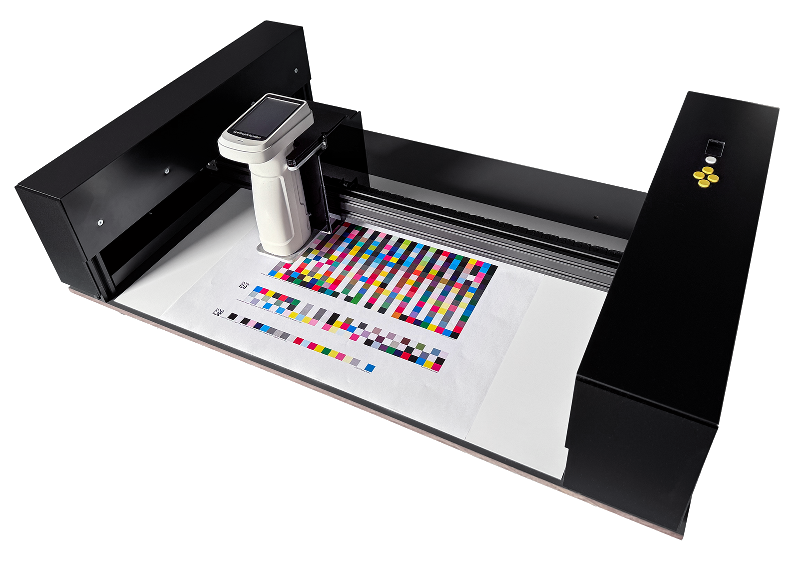
CC XY-table


Designed for:
- Scanning charts for ICC Profile creation or curve (G& or TVI) calibrations - thanks to CC Sphere support, can also be applied to metallic and other hard-to-measure surfaces.
- It can be used with the ChromaChecker Scan Match feature to control spot color reproduction precisely, now also when printed on metallic film (available soon).
- Quality control tasks on production sheets
Benefits:
- Turns portable devices such as CC Sphere or Nix into automatic XY scanning devices
- A typical working area of 330x500 mm can be customized ( e.g., 1120 x 840 mm)
- It can measure any sample with a thickness of 0-8 mm. The instrument suspension can be raised by an additional value for thicker objects.
- Suspended construction allows web measurements without cutting it - in both directions.
- The device is equipped with two laser red points, which allow for high-accuracy positioning of the instrument. Thanks to that, 6x6 mm patches can be measured with 2 mm Nix.
- The instrument can work in chart or Virtual Control Strip modes—there is no need to create control patches when the spot areas in the original artwork are big enough (feature available soon).
- Thanks to a CC -2D barcode reader support can be turned into an automatic measurement solution - this is especially recommended when working with Projects or Quality Control task
- Thanks to CC Sphere, it can be applied virtually to any postproduction finishing.
- It can be installed on any table or flat surface — only four mounting points must be prepared in advance. This allows it to integrate with any existing production environment.
Options are to be specified when ordering an XY-Table
- Expected working area size
- Backer — typically, we offer an ISO-compliant white backer — other options are black backing or no-table option (installation on customer table)
- Additional mechanical guides /stops help position samples on the table without the red-dot procedure. Depending on user preferences, various technical solutions can be applied (based on metal or plastic bars, metal sticks, or magnets-based solutions. The user may use double-side self-adhesive tape to make temporary stops. The typical thickness of samples and typical scenarios may determine the best selection.
- Integrated barcode reader
- Other custom requirements
XY-Table keyboard and display
|
On the right side is a small keyboard with the Enter key and arrow keys, which are used to control the XY-Table.
A typical situation to use the keyboard:
|
Preparatory procedures
Scanning templates
To work with CC Capture, the user has to define scanning templates. This is a typical procedure. For the XY-table, setting the location of the first chart corner is convenient. The value is expressed in millimeters from the top left corner. Once stored, it will drive the instrument into the proper location for position tuning based on red dot projection.
Calibration of the Red Dots lasers
The Red Dots should be calibrated after transport or a longer period of use. An effortless function called from the auxiliary application allows for correcting their position relative to the instrument aperture. The procedure is effortless and fast.
Draw a small dot on the paper. When the procedure is invoked, place the drawn dot in the place pointed by the Aiming Toll. In the next step, the right Red Dot will try to match the same point. Adjust with the arrow key correction and hit the Enter button. Repeat the same with the right laser. Finally, the Aiming point should show the same point again.
Adjust the thickness of the measured samples
Indicate how low the instrument will be lowered for the selected instrument and the measured samples—a dedicated function of the helper application allows for defining such a value.
Aiming Tool

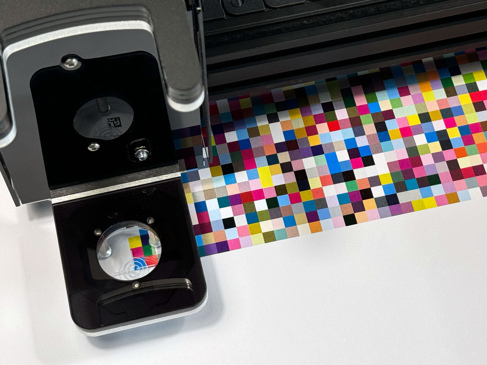
XY-Table comes with a dedicated Aiming Tool, which is required for Red Dot laser calibration and can help to check if patch size is optimal.
The cross-fair shows where the instrument will have a center point; three circles are 4, 8, and 12 in diameter - corresponding to the different sizes of the aperture.
Working procedure
- Select the scanning template - manually or using a bar-code reader.
- Hit the "Chart Config" button to tune the corner position. The instrument will move into the position defined as corner A in the Scanning template. The left Red Dot will show the current position - use the arrow keys on the instrument to tune the position. When done, confirm with the Enter key. The instrument will switch to the next corner. The instrument will inform which corner position is currently active.
- When all corners are defined, the instrument is ready to measure. The display shows a "GO" message. To start scanning, hit the Enter button on the instrument or the "Measure" button in the Capture interface.
The sequence visible on the XY-Table display is as follows:
![]()
![]()
![]()
![]()
![]()
Now, the user can repeat measurements as many times as required, and there is no need to define corners. The mechanical stops are used, and the sample can be replaced with new ones.
Please note that to ensure mechanical positioning can be used, a large patch size can be applied to compensate for positioning variations. Don't expect that 6x6 patches can be used with our Red Dot procedure in advance.
Evaluating potential positioning issues
There is a simple method for checking if patch size is optimally selected, especially when creating a solution based on mechanical stops that determine positioning. Connect your spectro directly to the computer — do not use a USB socket on the XY-table head. Place the Aiming Tool instead of the instrument. Lunch scanning template and observe if the cross-hair of the Aiming Tool has enough tolerance when hitting all points. This additional procedure helps to define quality control procedures as effective and reliable.
Understanding patch size limitations
By definition, the minimal patch size should be at least aperture + 4 mm for Red Dot calibration. Please note that ISO standards require at least 1 mm in radius, which means 2 mm in diameter. This is an assumption for perfect positioning. The XY-table uses hand-held instruments not designed to work in scan mode, so the integration time is relatively long. One millimeter extra means the user must pay attention to calibrating Red Dot lasers and defining corners with high precision. If not critical, use a patch size as big as possible to eliminate unwanted variations. Especially when mechanical positioning is preferred as the main method — additional positioning tolerance will make the solution more effective.
When defining positioning based on mechanical stops, please evaluate actual variations in the print run. The most critical part is to define realistic values for the system. It must be easy for the operator, so basing on mechanical stops is a great solution. Find a way to keep positioning without tightened tolerances.
Thickness Config
To launch this function, hit the "Thickness Config" button in XY-Table Helper. Be sure that the spectrophotometer is firmly installed in the XY-Table head. Prepare a sample with the proper thickness and place it in the middle of the table.
|
When the procedure is invoked, the XY-Table display
The functions of arrow keys are now: Up / Down - fine steps Left / Right - course steps |
Now, using arrows, move the instrument to the point where the sample is held and can't be moved. Do not use force; try short movements only. Optionally, prepare a sheet of very thin paper that can be used to see if it can be easily pulled out when the instrument is in a down position.
The instrument uses magnets to hold Spectro—too much force could potentially detach the instrument from the head, while too little would impact the measurements. Fine steps are small enough to find optimal value. The procedure usually takes less than a minute to perform. We recommend periodically relaunching it.
When thickness adjustment is done, hit the Enter button to store current settings.
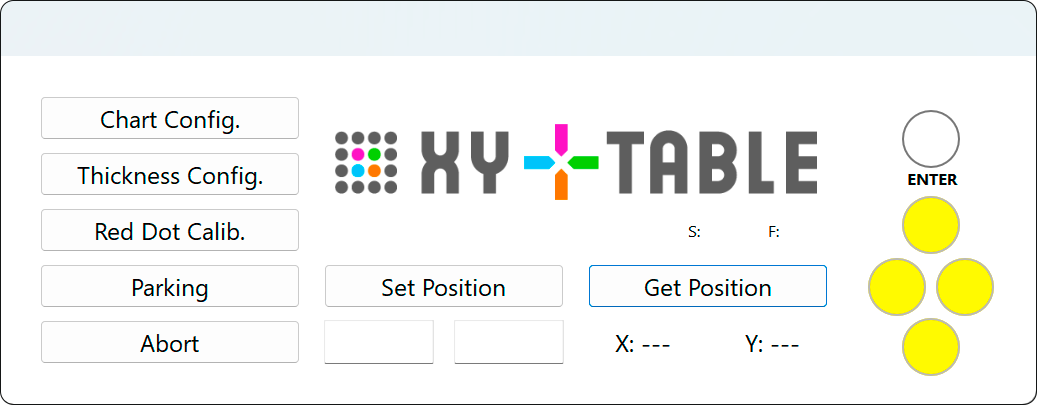
Helper interface

- Chart Config. invokes the process of pointing three corners. The laser will display a Red Dot, and the operator can fine-tune locations using arrow keys.
- Thickness Config. launches the thickness adjustment procedure. The typical range of samples that can be measured is about 8 mm. The user has to set the current value.
- Red Dot Calib. is a procedure for calibrating lasers. The idea is to have the aiming tool with the left and right red dots pointing to the same point.
- Parking — Move the head into the parking position, about 15 mm down and 15 mm right from the top left corner of the working area (coordinates 15, 15).
- Abort — stops the current process - head is going to Parking position.
- Get Position — reads the current head position - and helps to find a tuned coordinated position. This function is helpful for Scanning Template definitions and checking and editing samples in Virtual Control Strip.
- Set Position — jumps head to a given position.
Displayed icons
| Waiting for connection. Ensure the XY-Table is powered and switched on (green light), the USB connection is established, and CC Capture is launched with the XY-Table instrument selected. | ||
| Please wait. If it takes a long time - check the CC Capture log. | ||
| XY-Table is ready to select the Job. Select the Scanning template in the CC Capture interface. |
||
| You are ready to measure (positioned). To start, hit the Enter button on the XY-Table or "Measure" in the CC Capture interface. | ||
| Thickness Config Procedure. | ||
| An error was detected. Please consult the CC Capture log for more details. |
Working with NIX
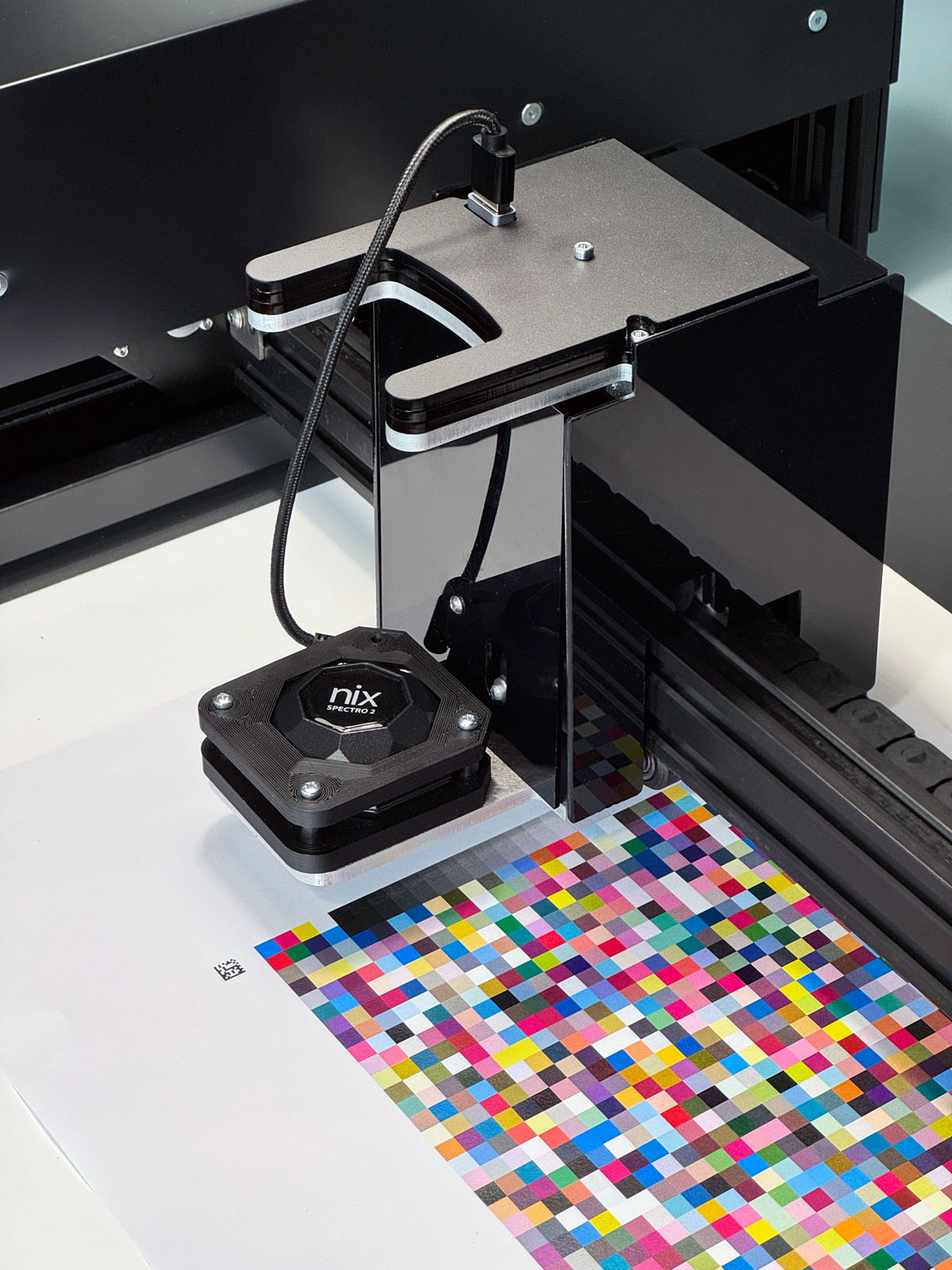
To use NIX, mount it into an adapter. Use three screws. Be sure to place it exactly as shown in the following picture.

The adapter can be placed in the head socket only in one position. It has two rounded corners (bottom) and two beveled corners (top). The USB socket has to be in the top left corner! There is only one way the instrument can be connected to the USB socket on the top of the head. Please be careful to make it the same way. Strong magnets hold the adapter — some force is required to detach it from the XY-Table head.
The typical measurement time is 3-8 seconds per patch, depending on the instrument. The XY-Table is waiting for data to move to the next patch—it is not a fixed value. Time can be different based on the measurement condition requested.
CC Sphere recommendations
CC Sphere is equipped with an integration sphere of 40 mm diameter—the largest aperture provides the best accuracy. We recommend using 11mm and patches of 17 x 17 mm (15x15 are possible). This is very demanding to point corners with high precision and calibrate Red Dots. Please note that SCI/SCE data for different apertures are not identical, and reference have to use the same settings.
Technical Specification of ver. S
- Physical dimensions: 800 x 510 x 200 mm
- Effective scanning area: 500 x 350 mm
- USB Type B connection socket (Mac or Windows)
- CC Capture — Build 1327+
- Power Supply: 12V 5A
Contact ChromaChecker Support
Additional information and Support Form is available for logged users.